Blitzortung.org
A World-Wide Low-Cost Community-Based Time-of-Arrival Lightning Detection and Lightning Location Network

Egon Wanke[1], Richo Andersen[2], and Tobias Volgnandt[3]
This document will continually change due to further developments and improvements. Please send your remarks to info@blitzortung.org.
Blitzortung.org is a world-wide non-commercial low-cost community-based Time-of-Arrival lightning detection and lightning location network. The system is made for private and entertainment purposes. The domain Blitzortung.org is not an official information service for lightning data. Commercial use of data from Blitzortung.org is prohibited, even by the users that send data to our servers.
This document can change without further notice. Publishing this document or excerpts of this document on websites not under our control is discouraged.
2 The Lightning Detector System Blue
2.2.2 H-field pre-amplifier PCB 16.x
2.2.3 E-field pre-amplifier PCB 17.x
2.3 Voltage regulator extension
2.4.3 Device Firmware STMicroelectronics Extension (DfuSe)
3 Setting up an Account for Blitzortung.org
4 The Antenna System should be 5
4.1 The electric antenna (E-Field)
4.2 The magnetic antenna (H-Field)
Either Ferrite Antennas or Loop Antennas
1 The Project
The aim of this project is to accomplish a low budget highly accurate world-wide lightning location network based on a high number of receiver sites spaced close to each other, typically separated by 50 km - 250 km. The stations transmit their data to a central computing server, where the strike locations are computed by the arrival times of the signals.
The station operators are volunteers who bought and assembled the hardware by themselves. There are also volunteer programmers who develop and/or implement algorithms for the location or visualization of sferic positions, and people who assist to keep the system running. There is no restriction on membership. There is no fee and no contract. If a receiver site stops pooling its data for a longer time period, the server stops providing the access to the archive of sferic positions for the corresponding user.
Blitzortung.org is completely different to other data collection platforms as for example marinetraffic.com or flightradar24.com. Ships and airplanes already know their exact position. They send their positions by radio. The information can be received with simple receivers and transferred over the Internet to a data server. Receiving and sending the received position is not time-critical and on their data server nothing needs to be calculated. The data is only collected and visualized. To receive the position of a ship or aircraft, one receiving station is sufficient.
Lightning location, on the other hand, is much more complicated. The waveforms of the signals must be sampled with high frequency (512 values at ≥500 KHz) and assigned with an accurate absolute time stamp (+/- 1 usec). The exact location of the detector is extremely important. An absolute microsecond accurate time stamp and an accurate position of the receiving detector can only be obtained by a GPS module. On computing server the signals from different detectors are adjusted and compared with each other. Each pair of signals from different detectors defines a hyperbolic curve. The intersection point of several hyperbolic curves determines the location. This is calculated on our server in a few seconds, that even professional systems do not always achieve.
2 The Lightning Detector System Blue
The Lightning Detector System Blue is a universal receiver for electromagnetic waves in the VLF/LF frequency range between 3 kHz and 300 kHz. It has three input channels for H-field antennas and one input channel for an E-Field antenna. The following two criteria played a crucial rule during the design of the detector.
1. The detector should not be too expensive for the end user.
2. The detector should provide the user with a variety of experimental possibilities.
2.1 The Kit
The main difference between System Blue and previous systems is that System Blue has partly prefabricated circuit boards. All surface-mount devices (SMD) are already soldered. However, there are still some components with leads that have to be inserted into holes drilled in the printed circuit boards and soldered to pads on the back side by manual assembly. For soldering you should use a soldering iron with a 1mm tip and thin solder wire. Do not try to solder these components if you do not have any experience with soldering electronic parts.
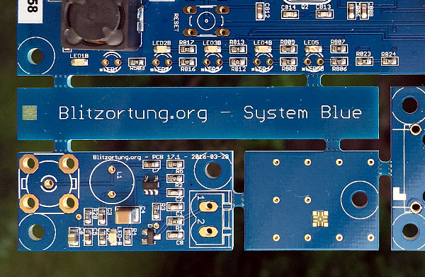
The board with the identification PCB 20.x is a panel consisting of a main board PCB 19.x an H-field preamplifier PCB 16.x and an E-field preamplifier PCB 17.x. The latest version of September 2017 is the panel PCB 20.5 with the main board 19.4 the H-field preamplifier PCB 16.1 and the E-field preamplifier PCB 17.1.
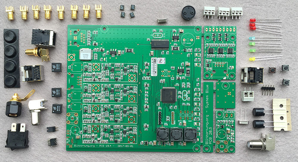
The following picture shows a complete set with all parts. Not all of these parts are essential for the operation of the detector. The 8 SMA jacks are not supplied. The maximal 4 filter ICs can be purchased separately and are not included as standard. The 3mm light-emitting diodes, the switch, the rubber feet and the grounding socket are only necessary if the main board is installed in the housing. These parts are only included if the housing is ordered.
2.2 The Assembly
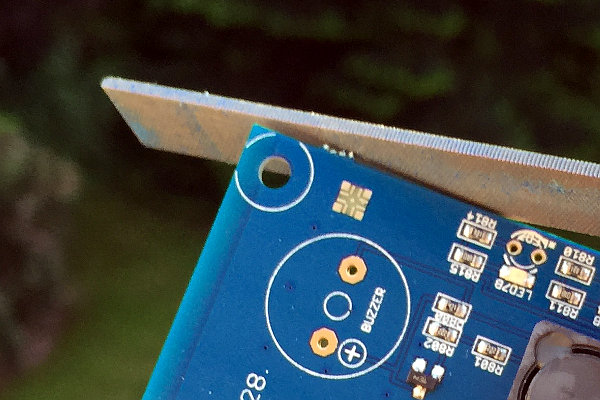
You can separate the boards manually. After that, you should file off the overhanging edges.
The schematics and PCB layouts can be found at
www.blitzortung.org/Compendium/Hardware/
2.2.1 Main board PCB 19.1/19.3/19.4
The main board PCB 19.x has the following through-hole technology (THT) components.
3 x DA103C - Transformer - Murata Power Solutions
1 x Inductor - 3.3 mH - Taiyo Yuden
1 x USB Mini-B Connector, PCB mounting, 90°
1 x 1x4 Header, straight, Pitch 2,54 (only 19.1/19.2/19.3)
1 x 1x5 Header, straight, Pitch 2,54 (only 19.1/19.2/19.3)
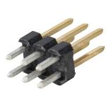
1 x 2x5 Header, straight, Pitch 2,54 (only 19.4)
1 x 1x2 Header, straight, Pitch 2,54 (only 19.4)
1 x 2x3 Header, straight, Pitch 2,54 (only 91.1/19.2/19.3)
1 x Jumper (only 91.4)
2 x Jumpers (only 91.1/19.2/19.3)
1x Piezo Audio Indicator
1x Crystal, 8.0000000 MHz
1x Crystal, 25.000000 MHz
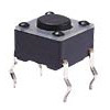
3 x Pushbutton 6x6mm, height: 4,3mm, vertical
1 x RJ45 Modular Connector
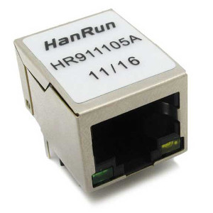
1 x HanRun (HR911105A) RJ45 network connector with integrated magnetics
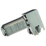
1 x F-Connector, PCB mounting, 90°
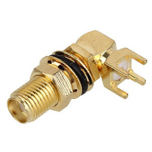
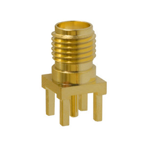
1 x SMA Connector, PCB mounting, 90°
1 x Ground Socket (only PCB 19.4)
Some of the THT components may have been soldered because they were required to install the initial firmware.

The DA103C Transformers have a white dot at one corner. On the main board, there are white dots printed at the placeholders for the transformers TR1, TR2, and TR3. The white dots at the transformers must match the white dots at the main board.

The 3.3mH inductor is L403.

Crystal Q1 has a frequency of 25 MHz, crystal Q2 has a frequency of 8 MHz.
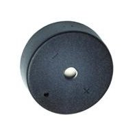
Some Piezo Audio Indicators have a ’+’-mark, which should match the ’+’-mark on the board. (If there is no ’+’-mark, then the orientation is not important.)
(only 19.1/19.2/19.3x)(only 19.1/19.2/19.3)


(only 19.4)


All other components can not be soldered at wrong places because of their physical layout.

The main board is supplied with a 5V USB power adapter. The plug must be a USB-B Mini 5 pin. The power supply is not part of the kit and must be purchased separately. The power consumption is about 450mA. Please use a 1A or bigger power supply. We have had some bad experiences with 500mA power supplies.

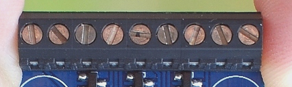
At switch S1 on PCB 19.2 you have to connect pin 5 and pin 6 with a jumper. This turns the board on, if a USB power supply is connected, shown by the red rectangle in the image below. You must connect pin 1 and pin 2 a jumper so that the pre-amplifiers get power, shown by the green rectangle in the image below. Note that these jumper settings are different from the early board PCB 19.1. Please refer to the circuit diagrams. At 19.4 you must connect the two pins of the power jumper.

The router is connected at the RJ45 network port with a shielded twisted pair network cable (FTP, STP, S/STP, or S/FTP).

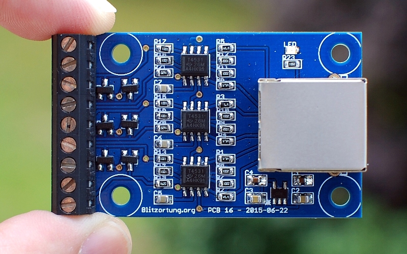
2.2.2 H-field pre-amplifier PCB 16.x
The H-field pre-amplifier board PCB 16.x has the following THT components whose placement is obvious.
1 x Header 3-pin, Pitch 3.5mm
1 x Header 6-pin, Pitch 3.5mm (or alternatively 2 x Header 3-pin, Pitch 3.5mm)
1 x RJ45 Modular Connector


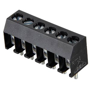
A-1 | A-2 | GND | B-1 | B-2 | GND | C-1 | C-2 | GND |
The antennas are connected to the pre-amplifier as shown above.
The H-field pre-amplifier is connected with a shielded twisted pair cable (FTP, STP, S/STP, or S/FTP) to the main board. This cable should not be placed next to the network cable. Please keep a distance of at least 10 cm. The cable may have a length of up to 30 meters.
If you use loop antennas, than you should close (solder) the jumper for the corresponding channels at the back side of the board.
If the pre-amplifier is powered, the red LED should light.
2.2.3 E-field pre-amplifier PCB 17.x
The E-field pre-amplifier board PCB 17.x has the following THT components whose placement is obvious.
1 x Inductor - 3.3 mH - Taiyo Yuden
1 x Header 2-pin, Pitch 5.08mm
1 x F-Connector, PCB mounting


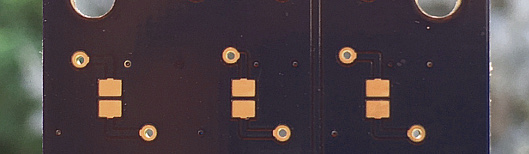
In panel PCB 20.1 and subsequent panels the free board space next to PCB 17.x is used as an experimental electrical antenna. This antenna is designed only for testing purposes. Due to a small manufacturer's error on Panel 20.5, the printed circuit board next to the E-field preamplifier is not connected to the input of the E-field preamplifier. Here, either a small solder bridge must be made or a corresponding antenna must be connected to the input. You can also break off this aerial and connect a wire antenna at the two pin header. The external connection point is ground, the central connection point is the antenna. Note that any electrical antenna must be placed outside far away from buildings and electrical interference sources.
The E-field pre-amplifier is connected with 75 Ω double shielded coaxial cable to the main board. The cable may have a length of up to 100 meters. The ends are attached to F-connector.
When the pre-amplifier is powered, the red LED should light. On the early pre-amplifier board 16.1 the green LED probably lights very weakly with a supply voltage of 3.3 volts. However, this is not a defect and is normal.
2.2.4 GPS antenna
You can use any GPS antenna operating with 3.5 Volts. The Antenna is connected via an SMA connector with the main board. The built in GPS module is very sensitive and works with antennas connected by lines of up to 10 meters.

2.2.5 Housing option
The housing option consists of the following parts.
1 x aluminum enclosure
1 x front panel
1 x back panel
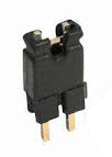
1 x rocker switch
8 x screw M3 10mm
4 x rubber feet
3 x LED red
2 x LED green
1 x LED yellow
1 x LED blue


The housing is made for boards of size 130.0 mm x 140.0 mm. The main board PCB 19 has the dimension 130.0 mm x 138.5 mm and is slightly shorter than the housing. The LEDs on the front panel are soldered with an angle of 90 degrees. The overlapping edge of the LED housing closes the gap between the board and the front panel. In this construction, the LED can not be crushed by pressure from outside at the front panel, which is the reason for the difference in size between the housing and the main board.

The threads at the corners in the aluminium housing are drilled by machine. Any protruding metal chips must be removed with a screwdriver or a wooden stick otherwise they may be fall onto the board. Do not use your finger to clean the threads.

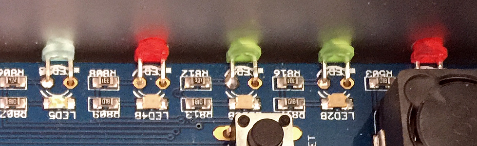
The connecting wires of the LEDs can easily be bent 90 degrees using the front panel that has a width of 2 mm. On the main board there are white stars printed near the LEDs. In these holes the short ends of the wires have to be inserted. This is the cathode (-) of the diodes.

At the back panel, the rocker switch can be inserted to turn the power on and off. It has to be connected to pin 5 and 6 of S1 (19.1/19.2/19.3) or at the power jumper (19.4).

The rubber feet can be stuck under the housing.

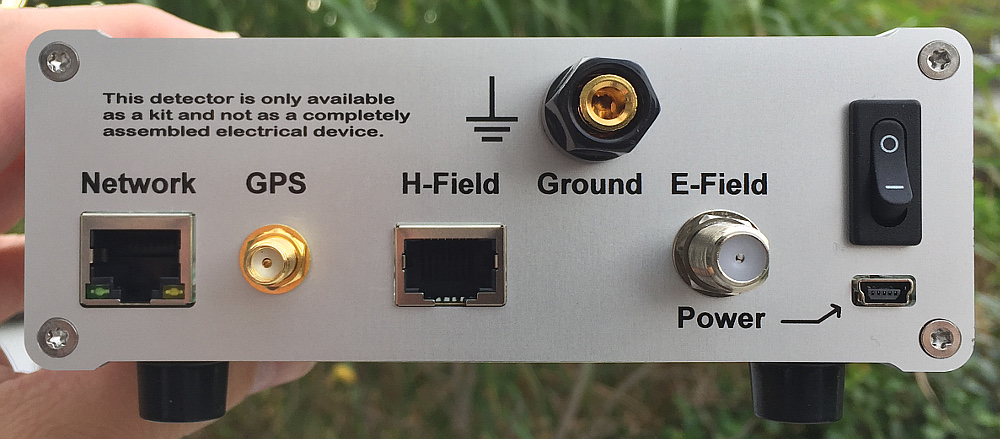
From version 19.4 a pole terminal for connecting ground is included. The layout of the back panel has also changed. The ethernet controller was placed a little further away from the amplifiers. The Ethernet socket has been swapped with the GPS socket.
2.2.6 Digital filter option
The complete digital filter option consists of
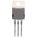
4 x digital filter ICs (LTC1569-7)
8 x SMA Connector, PCB mounting
In general, it is not necessary to install the digital filter ICs. The system also operates without them. However, if you want to experiment, or if you have extremely strong interference at frequencies above 20kHz, you can try to get better signals with the digital low pass filter ICs. Since the digital filter ICs are relatively expensive, you should test one filter IC at one channel, preferably at the E-Field channel. If the desired effect is achieved, the other channels can be upgraded.
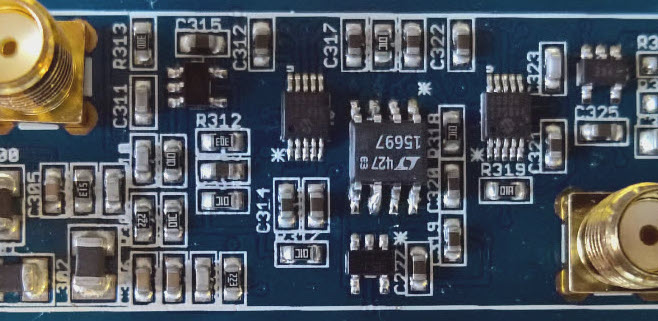
The digital filter ICs have a point at one corner of the housing. This point identifies Pin 1. It must match the white dot on the main board. You need a soldering iron with a small tip to solder the SOIC-8 package.
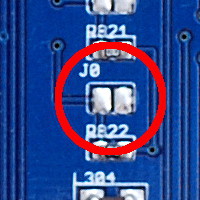
You have to close (solder) Jumper J0, otherwise the firmware will not recognize the filter ICs, and thus will not allow you to adjust them.
All inputs and outputs of the amplifiers are passed via buffer amplifiers to SMA connectors. If these connectors are installed, then the signals can easily be monitored with an oscilloscope or an FFT analyzer. There are various computer programs for signal analysis, if the output of the preamplifier is passed in to the PC via a sound card.
2.3 Voltage regulator extension
Unfortunately, the voltage regulators of the boards PCB 19.1 and PCB 19.2 are not adequate for the current consumption of the boards. This problem is eliminated by the piggyback board PCB 21.
The schematic of the board can be found here.


http://de.blitzortung.org/Compendium/Hardware/PCB_21_sch.pdf


PCB 21 is manufactured on a panel with severals boards and thus may have overhanging edges. You should file off these edges.

The voltage regulator IC502 should be unsoldered from the board. Please do not operate with both voltage regulators. They can act against each other.
2.4 Firmware
The firmware of the System Blue controller is pre-installed. When the device is turned on and is connected to a router, it gets an IP address via DHCP. You must check your router which IP address this is. Typically, the detector gets the same IP address after a reboot.
The firmware can be updated in three different ways,
- via the web interface of the firmware,
- via the Single Wire Debug (SWD) interface using a programming device, and
- via the USB interface using the Device firmware upgrade STMicroelectronics Extension) (DfuSe) interface.
2.4.1 Web Interface
To upgrade the firmware via the web interface, follow the menu prompts in the web interface.
2.5.2 Single Wire Debug (SWD)
The firmware can be upgraded via the SWD interface with the ST-LINK/V2 in-circuit debugger/programmer. This programming device is also contained at the STM32F4DISCOVERY board used for System Red. It is connected to the SWD interface as follows.

The software (STM32 ST-LINK Utility) for programming the controller with ST-LINK/V2 can be found on the website of STMicroelectronics.
The board additionally must be powered via the USB power supply during programming. The latest version of the firmware can be loaded from
http://tracker.blitzortung.org/firmware
Never flash a firmware for System Red on a System Blue and never flash a firmware for System Blue on a System Red. This can damage the hardware.
2.5.3 Device Firmware STMicroelectronics Extension (DfuSe)
You can also flash new firmware over the USB connector via the DfuSe of the processor as follows.
➡ If you are using a 19.x board, first connect the following jumper to the back of the board. This jumper is normally not closed to protect the processor from surges from defective power supplies.

➡ Load the DfuSeDemo software for Windows operating systems from the website of STMicroelectronics
or from the following site (the ZIP-file "stsw-stm32080.zip"):
https://tracker.blitzortung.org/firmware/dfu
For non-Windows operating systems you can use the following software.
➡ Install the application.
➡ Download a DFU firmware file for System Blue from the following site.
https://tracker.blitzortung.org/firmware/dfu
➡ Connect the System Blue controller board via USB to your computer.
➡ Start the System Blue controller in DFU-mode: Push and hold both, the RESET button and the BOOT0 button, at the same time. Then first release the RESET button before you release the BOOT0 button.
Your Windows PC should now recognize a new device and install a driver for the new device during the DFU setup.
➡ Open the DfuSeDemo application. You should see the message "STM Device in DFU Mode". If not, then something went wrong. Try Step 5 again (driver reinstall, check cable).
➡ Keep all setting as they are and click the "Choose..." button on the bottom. Select the DFU firmware file from above. Now it should look like in the following screenshot.

➡ Next push the "Upgrade" button.
➡ After the upgrade is done, you can push the RESET button or "Leave DFU mode" in the application.
➡ Now you should be able to access the webinterface to upgrade a more recent firmware.
The DFU mode is a feature of the processor itself and not a feature of our firmware. It’s not possible to overwrite/destroy the DFU-bootloader. That is, it should always be possible to recover the firmware after a failed web-interface firmware update. A DFU file can be created from a BIN file with the DFU file manager.
3 Putting the device into operation
If the board is built up, the first test should proceed as follows.
- Do not connect any preamplifier, do not connect the GPS antenna, and do not connect the network cable. Connect only the 5 volt USB power supply to the mainboard.
- On the mainboard the red power LED should be on, some of the other LEDs should flicker, and the buzzer should make some noise. If no LED is on and no sound is heard, then something is wrong with the voltage supply. Check whether a power switch is connected and whether it must be turned on, and check Jumper S1. Up to Version 19.3.c, Pin 5 and 6 of Jumper S1 have to be connected. From version 19.4, the two pins of Jumper S1 have to be connected, see Section 2.2.
- Next connect the board with your DHCP router. The network connector has two LEDs, a green one and a yellow one. The green LED should be on continuously. The yellow LED should flicker. If this is the case, then the network connection can be tested. Try to open the firmware web page with your computer. Go to the web page of DHCP router router and look for the IP address of the board. The hostname of the board is "blitzortung". Enter the IP address of the board in the address line of your browser such that you can see the webpage of the firmware.
- Familiarize yourself with the settings on the website of the firmware.
- Connect a GPS antenna until the blue GPS LED on the Borad starts flashing every second. Only then is the position fixed. This process can take a few minutes the first time. Please be patient. The GPS antenna should have visual contact to the sky.
- Connect an H-field or E-field preamplifier to the board. On the connected preamplifiers the red LEDs should be on. If this is not the case, something is wrong with the connection cable. Use normal CAT cable. It must not be a crossed cable. Touch the input contacts on the preamplifiers with a finger to generate a signal pulse. These signals should be displayed on the webpage of the firmware at the "Signals" page.
4 Setting up an Account with Blitzortung.org
On the top of the web page of the internal firmware web server you find a link to request an account for Blitzortung.org. This link is only visuable, if the station is not assigned to a ser ID. Follow the instructions in the email you will receive. The account is associated with your email address.
When you get an account, you will also get a user number. Users may have none, only one, or several stations. You can assign a station to a user account as follows.
Enter your username or email and your password on the login page of Blitzortung.org. After a successful login you are on the "Project Area -> User data" page. Here you can complete the information about you and your stations.
http://www.blitzortung.org/login.php
In the line "Assign a new station: (Processor ID)" enter the processor ID of your station. You find the processor ID of your station on the web page of the station under processor information.
4.1 Enter the internal Forum
Enter your username or email and your password on the login page of Blitzortung.org.
http://www.blitzortung.org/login.php
After a successful login you are on the "Project Area -> User data" page. Now change to the “Further Infos -> Forum” page.
http://www.blitzortung.org/forum.php
5 The Antenna System
We use Magnetic (H-Field) or Electrical (E-Field) antennas or both.
5.1 The electric antenna (E-Field)
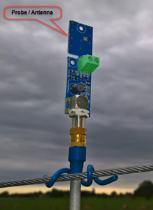
The “E-Field antenna” is a PROBE, a high impedance sensor that detects changes in the electric field between ground and atmosphere.
Use the built-in antenna, or a piece of wire, 10cm is fine, 1-2,5mm²
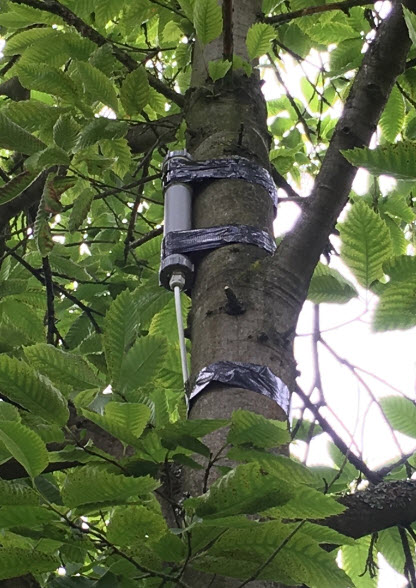
It should be placed high and far away from electrical installations.
Connect to Controller via 75 Ohm coax cable ( TV ) and an F-Plug
It is omnidirectional, and we use only one


5.2 The magnetic antenna (H-Field)
Either Ferrite Antennas or Loop Antennas may be used.
A magnetic antenna does not need to be mounted high since the magnetic field is not easily attenuated.
They must be a minimum of several meters from other electrical installations - In the garden just above the ground, attic, or on a balcony is ok.
Ferrite antennas 12 or 20cm can be purchased ready-made, or you can wrap them yourself.
10-12 cm is enough . 20cm is excellent. More than 20cm is unnecessary.
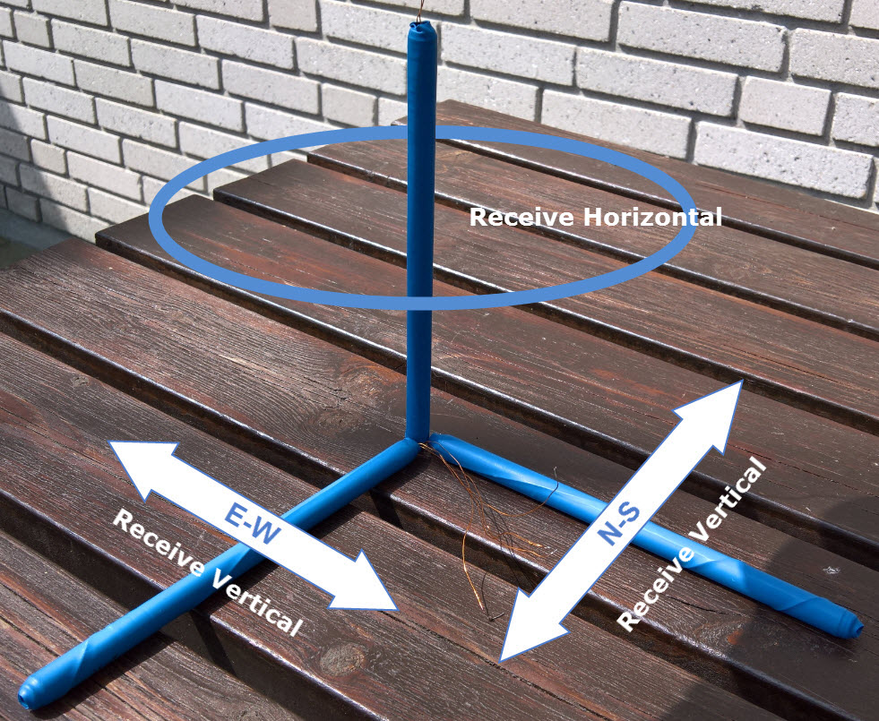
Should be mounted at right angles - cross or L-form
Electrical shielding is rarely needed as connecting to pre-amplifier is differential, and common mode signals are strongly attenuated.
We normally use 2 rods , but BLUE allows for an extra - which could be vertical.
Loop antennas can be made in many ways - in principle, it is just a conductive wire, wound as a coil.
The shape does not matter as it is the area of the total number of turns that determines the strength of the signal. Circular gives the largest area for a given length of wire, but a rectangular or any other shape, may be easier and is equally effective. Magnetic signals in a loop generate a current, so the wire used should be minimum of 0.75mm² and preferably thicker.
Examples
Wire Loop
3 turn, circle (100cm diameter) ~ Area = 0.5² * Pi * 3 ~ 2,4m²
Use 0,75mm² or thicker – lacque or plastic isolated copper wire
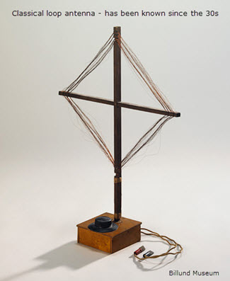
Wire Loop - “Classic”
Loop antennas has been knows since 30s, so it was obvious to start with this model
8 turn, square 100cm ~ Area = 8m²
Originally made for System GREEN - for System BLUE 3-4 turns is enough

Multi Turn.:
20 turn, (38cm diameter) ~ Area ~ 0.19² * Pi * 20 ~ 2,3m² (inductance ~ 500μH)
Use 1mm² lacquer or plastic insulated copper.

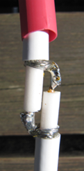
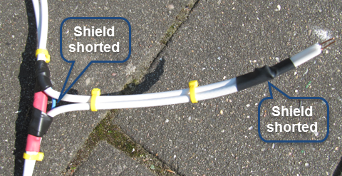
Coax Loop
A 3 turn, circle (100cm diameter) ~ Area = 0.5² * Pi * 3 ~ 2,4m²
Inner conductor to the terminal 1-2 and the screen from both ends to terminal 3 (shielding)
The screen must be broken at the midpoint, as shown below, so it does not short out the signal.

Möbius antenna

A 2 turn with a diameter of 1m gives a total area of 0.5 * 0.5 * 3.141 * 4 ~ 3,14m²
(0.5 x 0.5 x 3.141x 2)/4 = 0.39m2
(The cable is cut midway and the shield from one end is soldered to the inner conductor at the other end and vice versa - that way there will be 4 active turns)
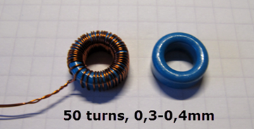
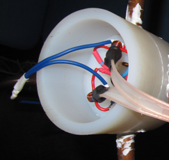
Antenna w/ with a current Transformers
Whether we use 4 turns of 1mm² or 1 turn with 4mm² is in principle gives the same result if we use a current transformer.
It may be convenient to use a thick copper pipe or copper bar for external antenna
This provides a relatively large current to be transformed to adapt the pre-amplifier.
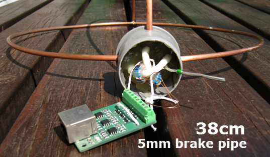
If we use a 50-turn toroidal current transformer as shown below, we get a relative area magnification of approximately 7 times.
A loop of Ø=38cm made of 5mm brake pipe gives a relative area of 0.38 x 0.38/4 x pi x 7 = 0.79 m2


Möbius antennas with a Transformer

Ø=38cm


General information about antennas
Preamplifiers are now so good that large antennas are not necessary.
Eg. the H-Field pre-amplifier has differential inputs and electrical common mode signals now have much less influence. Moreover, the amplifier has a gain of 10 times.
(However, the impedance matching to the input of the reduces the gain by 50% but provides excellent matching to the transmission cable and Controller input)
Connection to H-Field preamplifier
The preamplifier is supplied with an input impedance of 2k - which suits Ferrite ferrite antennas and antennas with transformer coupling.
Other antennas connected with 75 Ohm –must use the solder bridges on the back side of the PCB.
Coax cable and “coax cable”
For loops without transformer you can use the cheap sat-cable with copper-plated iron wire.
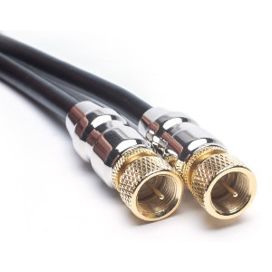
Loop antennas with a transformer, must use coax with pure copper and heavy shielding i.e. (75 Ohm 8mm cable as used for radio and TV-set for decades.)
No antennas must be grounded at the antenna.
It may be a good idea to ground the Controller.
One or more antennas
Your receiver works fine with either an H-Field or an E-Field antenna.
Both types have their advantages and disadvantages
You can easily start with one of them, and then install the other later, or settle for one.
[1] Düsseldorf, Germany,
[2] Nakskov, Denmark
[3] Roßtal, Germany